Plan Service from Trends: Motor Vibration Monitoring at a Production Site in Thailand
A single reading can't tell normal variation from a developing problem. Vibration sensing with S09 tracks trends so servicing and spare parts can be planned ahead.
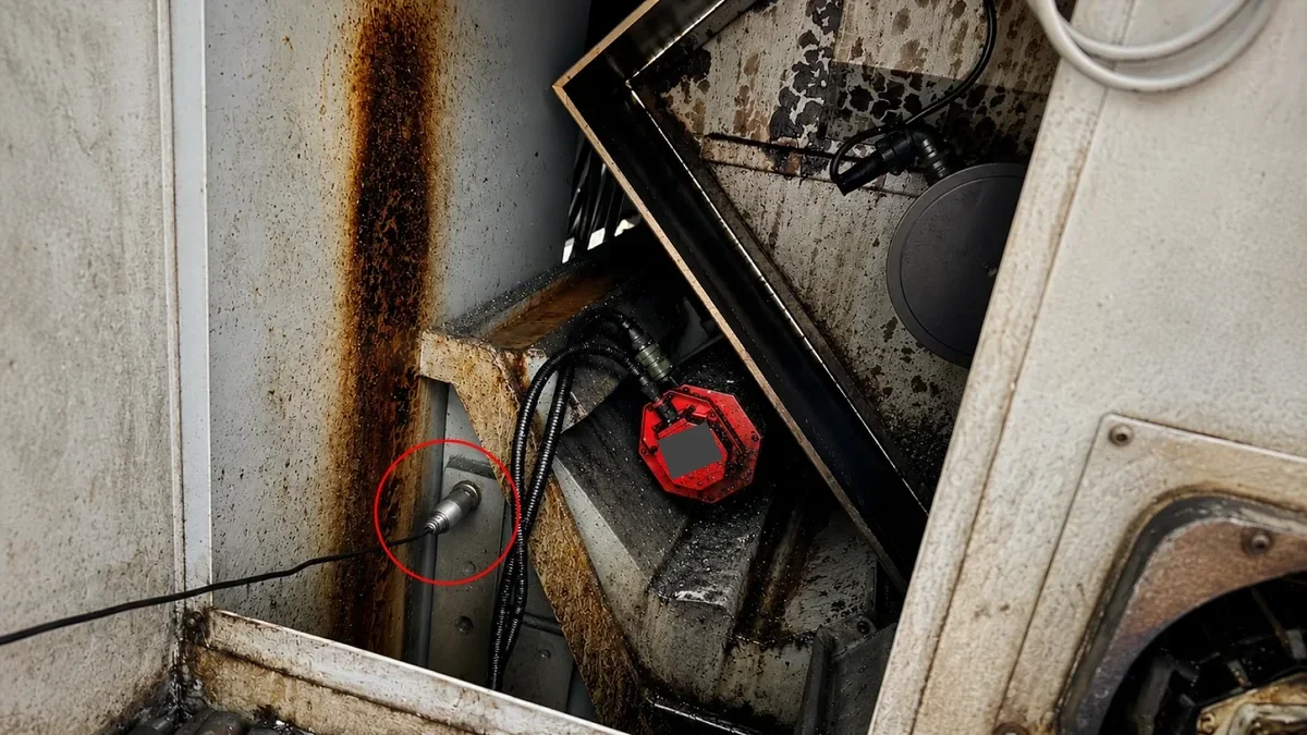
Image: vibration-sensing point on production equipment.
Project Profile
- Region: Thailand
- Category: Industrial
- Deployment Status: Formally deployed
- Product Configuration: Vibration-sensing configuration + S09 Smart Wireless Transmitter
Deployment Highlights
- Baseline Comparison — Establish a reference under representative site and equipment conditions, then review deviations over time
- 5-Stage Workflow — Baseline → deviation → verification → planning → maintenance
- Field Interpretation — Combine the trend with load, speed, temperature, sound, and on-site inspection
- Interpretation Boundary — A trend deviation prompts review; it is not a standalone fault diagnosis
Case Snapshot
A production site in Thailand has formally deployed a vibration-monitoring workflow for rotating equipment. A site-specific vibration-sensing configuration captures equipment-condition data, while the S09 Smart Wireless Transmitter relays the data for trend review. This allows the maintenance team to compare current equipment behavior with an established baseline and monitor deviations over time.
The deployment serves as an early screening layer. When a trend moves outside its normal band, the team verifies the equipment condition on site before deciding whether to prepare replacement parts, reserve a maintenance window, or continue observation. The workflow turns distributed readings into a traceable maintenance input while preserving the engineering judgment required for field verification.
Problem
A single reading cannot distinguish normal variation from a developing change
In a continuous-production environment, motors and transmission components operate under changing load, speed, temperature, and production conditions. A single reading does not show whether a change is temporary or developing over time, while inspection rounds may not capture the same operating state on every visit.
The maintenance team needed a repeatable way to compare equipment behavior across monitoring periods without treating every deviation as a confirmed fault.
Solution
Establish an equipment baseline, then use deviations to trigger verification
Each monitored point first establishes a reference baseline under representative operating conditions. Subsequent readings are compared with that baseline band so sustained or increasing deviations can be identified.
A deviation starts a review rather than an automatic diagnosis. Maintenance personnel combine the trend with operating load, speed, temperature, sound, and an on-site inspection before choosing the next action. This keeps the monitoring layer useful without overstating what vibration data alone can prove.
Related Field Evidence
Vibration trends from the new-tool period through tool wear can support tool-change planning
The following is independent field evidence from a related machine-tool and lathe spindle-motor application. It is presented separately from the Thailand deployment to illustrate the same vibration-trend interpretation logic.
This field application used single-axis vibration measurement as its initial phase. Vibration amplitude remained comparatively low and stable during the new-tool period. As operating time increased and the tool gradually became dull, higher amplitude and vibration frequency were observed. The team could therefore use the trend as one input for tool-change planning, together with machining quality, equipment load, and on-site inspection results.
This approach can help teams schedule tool changes earlier and reduce the risk of tool breakage and unplanned downtime. It does not guarantee that failures or downtime will be avoided. Thresholds must be established for the specific machine, tool, machining conditions, and site baseline.
Deployment Value
Maintenance planning gains an earlier, traceable screening signal
Trend visibility gives the team a common record for deciding which equipment deserves closer attention. When a deviation persists, inspection, spare-parts preparation, and a maintenance window can be considered before the issue becomes an urgent response.
This case does not claim a measured reduction in downtime, labor hours, or failure rate. Its documented value is the adopted workflow: equipment condition is screened against a baseline, exceptions are verified, and maintenance actions can be planned with clearer context.
Future Engineering Options
Where more detailed directional comparison is required, a project may evaluate three-axis sensing, frequency-domain analysis, or AI-assisted interpretation. These are future engineering options subject to equipment conditions, data quality, sample volume, and engineering validation. They are not standard S09 functions and do not replace on-site diagnosis.
Next Step
For a similar deployment, define the monitored asset, sensor position, representative baseline period, review owner, verification method, and escalation criteria before setting any alert rule.
Explore Solutions / Talk to an Expert
Sensing Position Images

Image: close view of the sensing position on the machine.
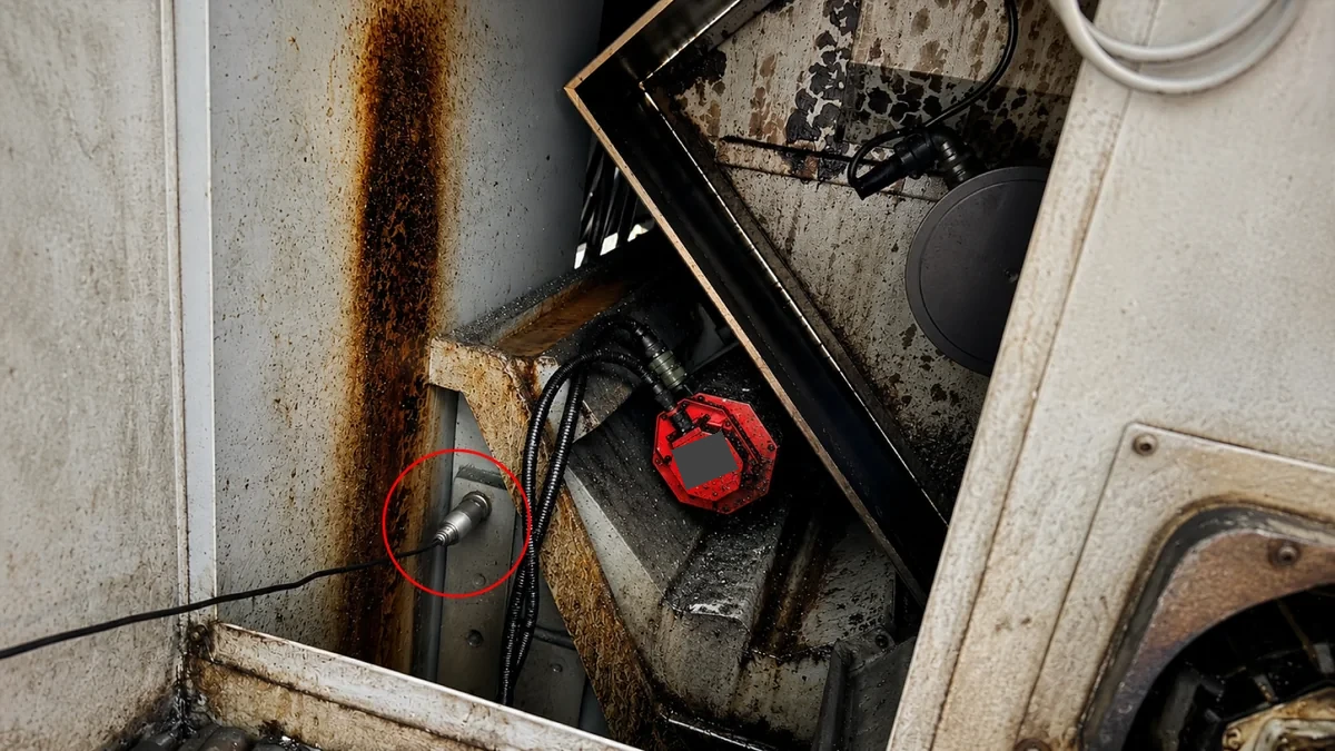
Image: sensing equipment and machine configuration.
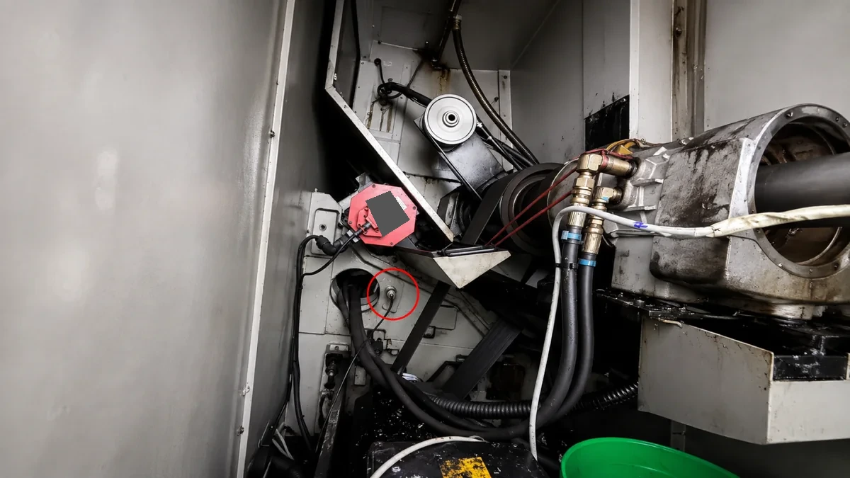
Image: monitored point on production equipment.
Trend and Workflow Illustrations
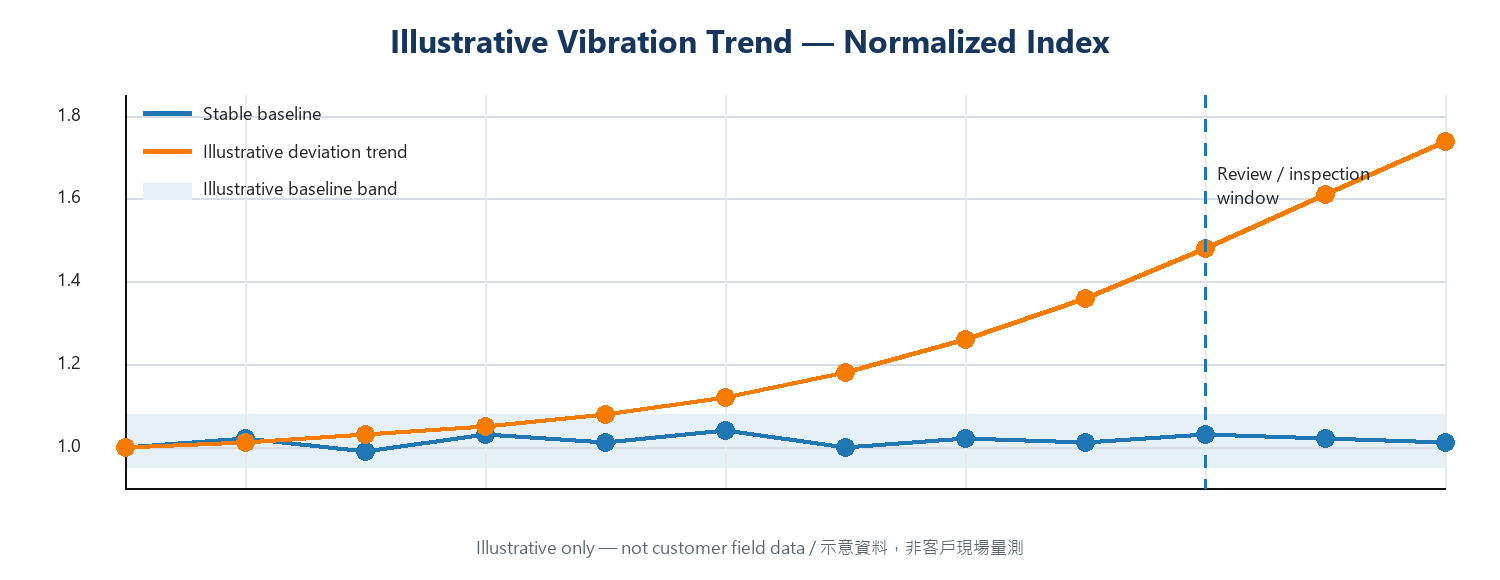
Trend interpretation illustration; not customer measurement data.
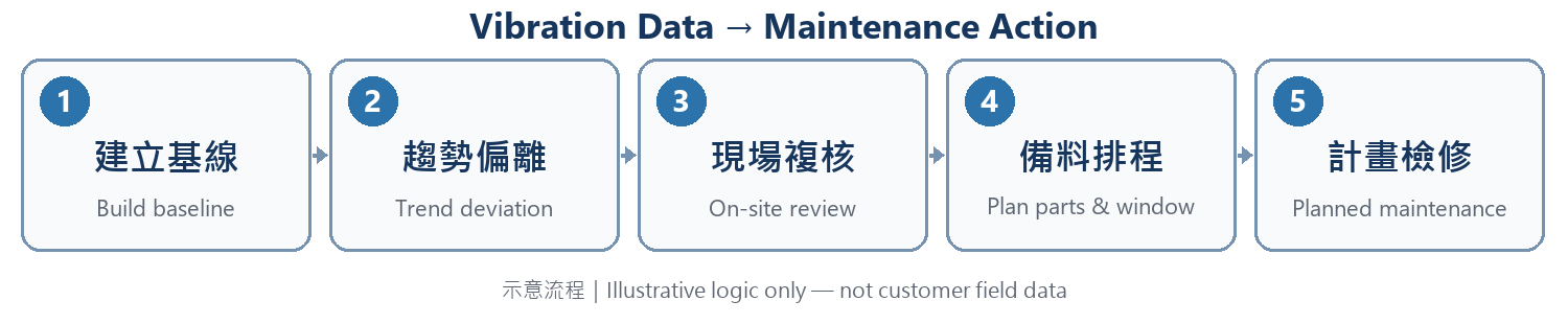
Workflow illustration; not customer measurement data.
Notes
- Every site is different; deployment plans and outcomes should be assessed by qualified professionals against actual site conditions.